Meeting the Challenges of 5G RF Production Test Services
Implementation of the 5G radio frequency (RF) standard is increasing rapidly [1]. Over the past four to six quarters, there has been an increased focus on publications and products that have been introduced to the marketplace. Some of the more popular RF eco-system applications include cellphone, WiFi, automotive, Internet of Things (IoT), location services, and more. WiFi and cellphone services are data-intensive, while IoT, in some cases, might require a limited amount of data.
Based on the 4G mobile network’s unit volume metrics, the confidence levels on achieving the unit volumes in Figure 1 and total addressable market (TAM) with 5G standards definition appear to be high.
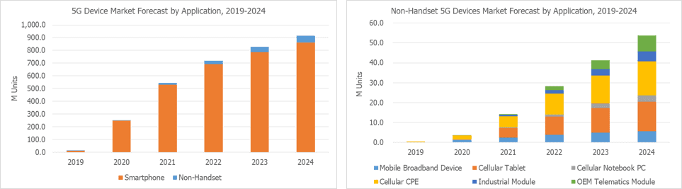
Figure 1:Strong growth is predicted for 5G products.Source: IoT Business News.
There are plenty of similar plots showing such volumes from worldwide geographies developing products to 5G specifications. Higher 5G RF unit volumes are expected to result in higher unit volumes at test. Infrastructure developments and deployments are expected to precede the user equipment introductions. As shown in Figure 2, a typical cellphone application includes a base station with cellphone towers, each of which supports multiple users’ cellphones in the coverage area.
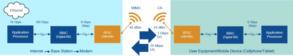
Figure 2:Key ingredients of a two-way RF communication block diagram include an application processor (AP), baseband integrated circuit (IC), and radiofrequency integrated circuit (RFIC).
由于基站suppor的覆盖范围t multiple user equipment, the RF power requirement is higher relative to the user equipment. Base stations are powered by plug-in power, while the user equipment is designed to be power efficient because they are mobile and battery-powered. Since the magnitude of data downloaded on a typical cellphone is a couple of orders of magnitude higher than the data uploaded, the number of receive channels is typically larger than the number of transmit channels. Concepts like multiple-input, multiple-output (MIMO), and carrier aggregation (CA) [1] are employed at a protocol layer to increase the effective bandwidth. Receive channels employ diversity [1] to improve spatial performance. Even though these concepts are not the direct focus of this article, product architecture and design do have an impact on test requirements and test methodology. WiFi technology-based applications are typically within the home/office. Their maximum RF power is limited, yet the dynamic range is not, and their bandwidth is typically higher relative to cellphones.
The recent introduction of the 5G 3GPP standard [1], identifies carrier frequencies in two separate carrier frequency spectrums. As shown in Figure 3, FR1 carrier frequencies are in the 410 MHz to 7.125 GHz range and the FR2 carrier frequencies are in the 24 GHz to 52 GHz range. The allowable bandwidths exceed 100 MHz up to 2 GHz. The sub-carrier spacing is compacting and hence the need for tighter constraints for phase noise and gain flatness.
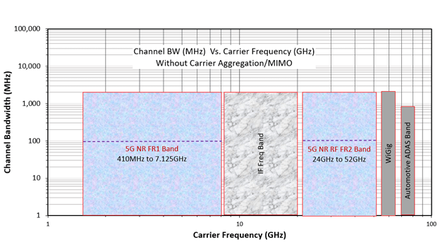
Figure 3:The 5G carrier frequencies are defined in the 3GPP specifications [1].
5G 新無線 (NR) 変調方式
There are two 5G NR signal modulation schemes – cyclic prefix orthogonal frequency division multiplexing (CP-OFDM) and discrete Fourier transform spread orthogonal frequency division multiplexing (DFT-S-OFDM) [1] (Figure 4).
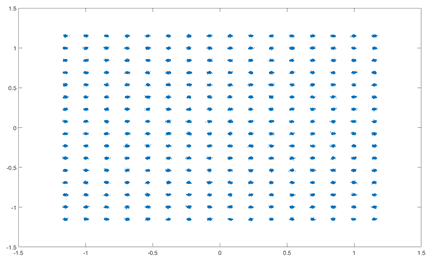
Figure 4:A 256 quadrature amplitude modulation (256-QAM) 5G NR constellation plot captured on an Advantest V93K.
CP-OFDM is for downlink (D/L), with quadrature phase-shift keying (QPSK), 16-QAM, 64-QAM, and 256-QAM. It has high spectral efficiencies and is compatible with MIMO and 4G LTE definitions. DFT-S-OFDM is for uplink (U/L), with π/2- binary phase-shift keying (BPSK), 16-QAM, 64-QAM, and 256-QAM. It has a more complex implementation and has less flexible resource assignments compared to CP-OFDM and it is not used in combination with MIMO. The five sub-carrier spacings for 5G NR are between 15 kHz to 240 kHz. Figure 4 shows a 256-QAM plot.
5G RF 製品と RFIO
Modern direct and heterodyne converter architectures [2] have digital baseband I/O. The digital baseband feeds the data to a digital-to-analog converter (DAC) that creates the analog in-phase and quadrature (I/Q) waveforms. These waveforms, when mixed with a local oscillator (LO) signal, up-convert the data to produce the modulated intermediate frequency (IF) or RF signal that is transmitted to the receiver (Rx). The signal transmission occurs over a coaxial shielded cable or over the air. Prior to transmission, especially when it is over the air, the signal may require signal amplification. Also, the receiver may require the received signal to be amplified prior to supplying the signal for down-conversion. The down-converted signal is fed to an analog-to-digital converter (ADC) that converts the signal to digital baseband for processing by the application processor. Figure 5 shows these steps.
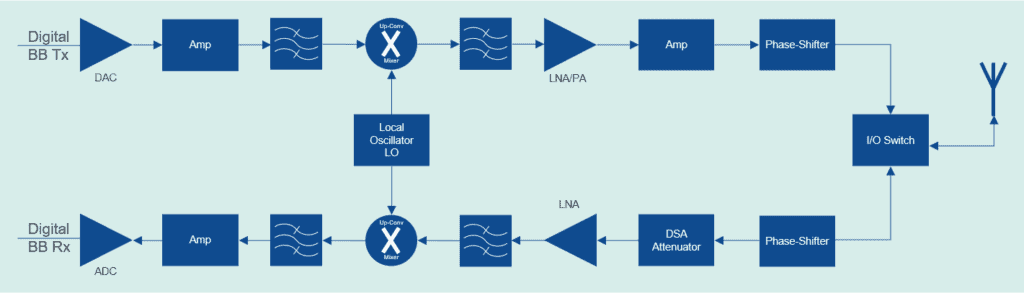
Figure 5:Simplified transmitter (Tx) and Rx RF chain blocks.
Integrated device manufacturer (IDM) customers bring a variety of RF products for assembly and test services. This includes, and is not limited to transceivers, low-noise amplifiers (LNA), power amplifiers (PA), digital step attenuators (DSA), filters, and mixers. Depending on the target application, the number of RF input and output channels may be different. Bandwidth, phase noise, intermodulation distortion (IMD), phase and amplitude resolution/accuracy, and other test requirements may vary as well.
The device under test’s (DUT’s) transmitter characteristic specifications for production testing includes transmitting power and RF spectrum emissions (occupied bandwidth, out of band emissions, adjacent channel leakage ratio (ACLR), and IMD). DUTs Receiver characteristic specifications for production testing include receiving sensitivity, maximum input levels, adjacent channel selectivity, blocking, spurious response, and IMD [1].
5G RF サブシステムを搭載した自動検査装置(ATE)テスターとツーリング
Advantest, Teradyne, National Instruments, and Cohu have recently publicly released an upgrade path for their mature ATE offerings. Amkor utilizes ATE’s RF sub-systems hardware and software instrumentation infrastructures to test customer products in production factories.
ATE vendors typically architect a universal superset configuration of instrument resources for customer test application development. The number of arbitrary waveform generators (AWGs), digitizers (DGTs), LOs, filters, amplifiers, tone combiners, transmit signal splitters, receive signal switches and their wide bandwidth and dynamic range of operation present trade-offs that must be considered for every new 5G RF application for each customer. Phase noise at application-specific frequencies and amplitudes from the instrument design has a direct impact on the error vector magnitude (EVM) test. Phase noise of -110 dBc/Hz at an offset of 100 kHz and -10 dB or better is acceptable (typical) at 5G range of continuous wave (CW) frequencies. In typical broadband customer product applications, there is a need to switch frequencies and amplitudes. Switching times impact the overall test list execution times. Testers with the smallest switching times are the most efficient in production testing. Figure 6 shows an ATE block diagram.
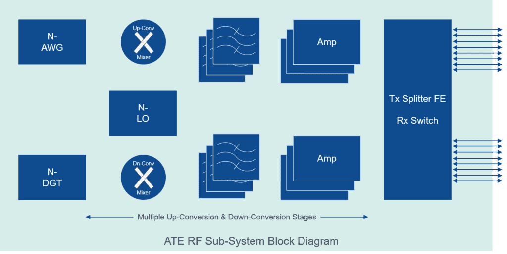
Figure 6:A simplified ATE block diagram.
Custom tooling (probe cards and/or load boards) must be developed to help route tester resources to devices, pins, or bumps. For wafer probe services, probe card vendors deliver probe pin technologies. For 5G RF carrier frequencies that are above 50 GHz, the challenges include impedance matching and pin to pin and site to site signal isolation. For packaged parts, load board, socket, and socket-pin technology vendors deliver pin technologies. For 5G RF carrier frequencies, challenges are similar to the ones described for probe pins. Acceptable levels of insertion loss (S-parameter S21) at these frequencies are typically no more than -10 dB and return losses (S11) over the frequency range are typically better than -10 dB. Acceptable levels of pin-to-pin isolation for typical applications are better than -45 dB over the range of frequencies.
RF performance and accuracy specifications are guaranteed by the supplier to the test head signal delivery interface. The tester supplier develops and delivers calibration systems (hardware and software) to calibrate, verify, and diagnose performance within documented specifications. RF instruments’ accuracy specifications are sensitive to temperature fluctuations. In most cases, a ±5°C (or tighter) change in temperature triggers the instrument’s self-calibration routines. Power, signal (digital, analog/RF), and clocks require moving the calibration plane from the test head to the device pin. This path includes the traces on the probe card or load board. We have a unique benefit of either employing de-embedding techniques and using loopback or custom-developed Short, Open, Load, Through (SOLT) structures to help deliver the required RF signal accuracies to the device under test. Developing custom standards for calibration in most cases requires additional efforts, however, with in-house package designs, the avenue does exist. In most cases, golden loopback DUT techniques have been sufficient to achieve the desired accuracies.
Assembly-Test Attach
Our Assembly and Test divisions work closely to enable 5G RF engineering development followed by production testing. The benefit is a complete assembly and test turnkey solution offered from the same factory location. 5G packages offering antenna in package and antenna on package (AiP/AoP) SIP were first produced by Amkor in July 2018 and announced in a public press release in 2019 [3].
最近进步ments in assembly and packaging technologies, RFICs, like 5G transceivers and RF Front End (RFFE) devices, may have antennas embedded within the package. Similarly, System in Package (SiP) devices have integrated relevant components like processor, memory, RFIC peripherals, discrete components including power amplifiers, low noise amplifiers, phase arrays, and antenna structures within the IC package [4]. The antenna forms the critical component of the front-end and requires tuning for the specific frequency band of operation. The 5G NR FR2 compliant customer products being designed today have their performance-tuned in specific operating bands, as defined in the 3GPP specification [1]. Data-intensive applications may warrant packing multiple radios within the package and hence the need for multiple antennas tuned per frequency band of operation.
All production testing of previous and present generations of RF devices has been conductive. RF I/O from and to the DUT are electrically connected with impedance-controlled paths over cables and shielded printed circuit board (PCB) micro-traces to the tester’s RF instrumentation. As described above, all ATE suppliers developing 5G RF test solutions include a conductive RF coaxial interconnect. To enable high-volume production testing of packages with an embedded antenna, the test methodology requires an interconnect that can transmit or receive RF energy with minimal and controlled signal loss. Antenna transmission theory [7], requires minimal spatial separation between the transmitter and the receiver. This separation depends on the carrier frequency. The number of RF I/O channels and multisite test requirements add to the production test complexity. The test options that are presently being explored, include patch and horn antennas, beamforming ICs (BFICs), embedded directional couplers, and waveguides. None of these solutions is high-volume manufacturing friendly nor are they scalable as the number of antenna increases. This is primarily due to the physical space requirement in the handler at the tester interface.
IDMs have been architecting design structures that allow loopback Design for Excellence (DfX) modes on transceivers to help simplify and make production test equipment requirements economical. While an antenna embedded within the package offers added miniaturization and overall integration, it does take away the flexibility of final performance tuning of the application for the new 5G NR operating band of carrier frequencies. The company continues to partner with suppliers and customers to solve the over-the-air (OTA) test challenges for production testing.
付加価値の提案
大きく分けると、テストモデルには主に2つのものがあります。一つ目は、お客様がすべてのテスト内容を管理し、5G RF テスト機器のコンサインなどを行ってAmkorに製造を委託するモデルです。二つ目は、量産テストを可能にするために、当社がお客様の要望に応じたエンジニアリングサービスを提供することです。この場合、弊社のテスト開発チームはお客様と密接に連携し、お客様のテスト開発エンジニアリング(TDE)要件のカスタムニーズに対応します。付加価値 TDE サービスの例としては、以下のものがありますが、これらに限られるものではありません。
- 最適な5G 対応テスターの選択、
- 最適なプローバやハンドラーの選択、
- 特にマルチサイトの量産テストのために,テスターのリソースを適切に割り当てができる最適な5G テストツール(プローブカード、ロードボード)の設計、
- Developing and debugging production test programs, test patterns, and test waveforms per the customer’s functional test specification,
- 製品認定、
- 製品特性検査のルーチン、
- Yield optimization, low yield failure analysis, and product design feedback. (Failure analysis may, for example, require X-ray or de-lamination to determine the root causes of fabrication and assembly packaging defects.),
- 完成品も効率的に取り扱いできるカスタムのバックエンドフロー。
The RF test development engineering group has significant experience developing test solutions and test content for previous and present generations of RF technologies and continues to build upon this expertise to solve 5G test challenges described here. The group is actively engaged in creating and proposing test solutions for base station and mobile 5G RF products in both FR1 and FR2 RF spectrum. These test solutions make use of the 3GPP standard-compliant ATE hardware and software test tools described above.
Internal production test processes have matured over the years and allow the implementation of design for manufacturing (DFM) rules to 5G RF production testing. Collecting, analyzing, and retaining manufacturing test results of 5G RF production tests is vital for incremental improvements to test methods, flows, and content. In specific cases, test engineers provide valuable feedback to the IC design and fabrication process engineers. Established statistical bin limits (SBL) for 5G RF test results for multisite across the test equipment fleet can help identify systemic equipment-related false failures and help with the elimination of such factors. This ensures optimal test equipment utilization and improves the overall production throughput.
A good portion of customers have products with critical time-to-market (TTM) goals and are sensitive to intellectual property (IP) contamination and security. Mature systems and processes are in place to handle all such customer concerns.
Amkor production test has been preparing to test the large number of 5G products that are expected in the coming years. This includes the 5G base station and infrastructure equipment that is expected to precede user equipment (mobile devices) growth.
サマリー
The 5G RF production test business is substantial in size and growing rapidly. Our production test teams have been working closely with assembly packaging, ATE suppliers, and customers to ensure that holistic 5G RFproduction test servicesare made available to meet and exceed all test capability and capacity challenges.
参考資料
- 3GPPTS 38.101-1 V16.1.0 (2019-09).
- Wide Band RF Architecture options – Peter Delos,Analog Devices.
- Amkor Device Packages
- Antenna In Package/Antenna On Package
- 公司天线在包Article.
- Amkor Packages – Press Release 2019
- Fresnel Far Field RegionorAntenna Theory
著者
老主任Vineet Pancholi测试技术kor Technology, Inc. in Tempe, AZ. Vineet joined Amkor in January 2019 and currently leads test technology development for 5G RF and high-speed digital production test methodologies. Before joining Amkor, Vineet worked in test development at Microchip Technology. Prior, he spent 19 years at Intel in a variety of test roles, including tester supplier management, test technology development (burn-in, final and system level test) and RF tester architect. Vineet holds a patent on semiconductor device testers and has earned master’s degrees in physics and electrical engineering from Arizona State University.
関連する記事

Amkor Technology China Recognized By GOODIX Technology, Inc.

パッケージングの導電密度増加